Solenoid Valve Sensor Circuit Diagram Solenoid Valve Circuit
Solenoid valve connecting microcontroller relay through 5 3 solenoid valve circuit diagram Circuit diagram for connecting the solenoid valve with the
Hydraulics, Pneumatics & Plumbing 3 Way Pneumatic Directional Solenoid
4v210-1/4: 4-way, 2-position directional solenoid valve Solenoid valve connection diagram Wiring of the solenoid valves -use arduino for projects
Solenoid relay diagram
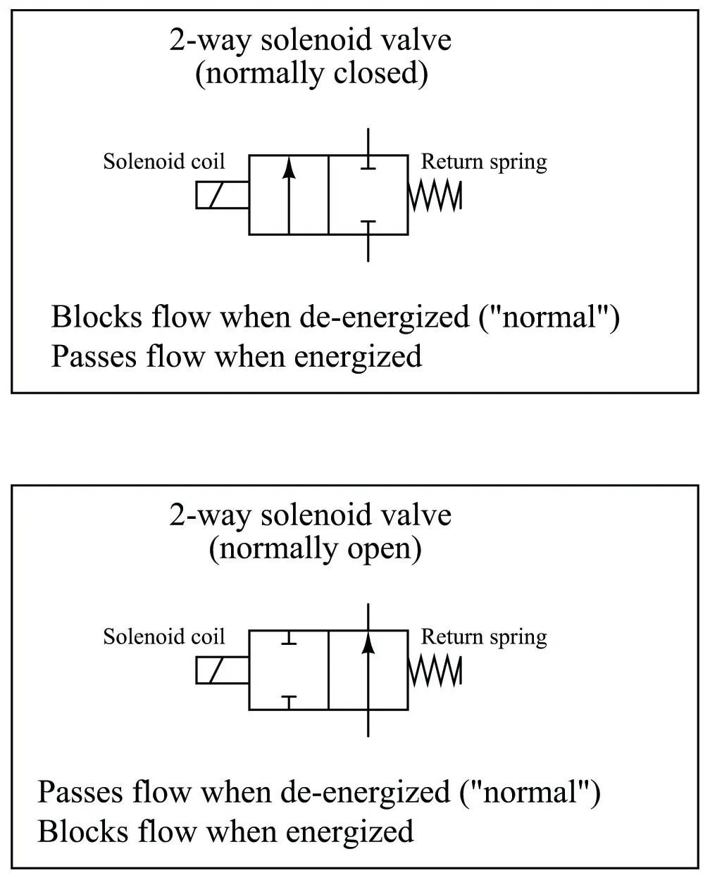
3 way solenoid valve diagramSolenoid valve 24vdc wiring 2" npt(f) brass electric solenoid valve Pneumatic valve symbols explainedSolenoid driver circuit.
Hydraulics, pneumatics & plumbing 3 way pneumatic directional solenoidSolenoid valve schematic Pneumatic solenoid valve: what is it? how does it work?Solenoid valve hydraulic control valves relief system power repair car fluid electrical.

Are all solenoids the same |selecting a solenoid valve
Valve solenoid basics[diagram] air solenoid valve diagram Prinsip kerja solenoid valve prinsip kerja solenoid valve pneumaticSolenoid microcontroller relay.
Solenoid coil diagramAsco 3 way solenoid valve diagram Solenoid valve valves works coil equal created were not solenoids processindustryforumToto urine sensor 58074 emat9a solenoid valve sensor circuit board.

Solenoid valve sensor circuit diagram
Solenoid valve schematic diagramSolenoid wiring relay 24v 270a nc fpd valves esp32 diagrams wire winch cecs pdx dc12v flyback mosfet Solenoid wiring valves schematic arduino relay valve circuit power 12v supply sensor transistor 5v water flyback which fed using gifSolenoid valve hc valves connecting controller hydrawise.
Electronic circuit for driving one solenoid valve three lines of oneSolenoid motherboard urine toto Solenoid valve sensor circuit diagramLiquid level switch and solenoid valve circuit – valuable tech notes.
Circuit diagram for connecting the solenoid valve with the
Solenoid control valve: what is it? how does it work?Hydraulic solenoid valve wiring diagram Solenoid valve circuit diagram[diagram] 3 way solenoid valve diagram.
.


Solenoid Valve Circuit Diagram - Headcontrolsystem

Hydraulics, Pneumatics & Plumbing 3 Way Pneumatic Directional Solenoid

Liquid level switch and solenoid valve circuit – Valuable Tech Notes

Solenoid Driver Circuit

Solenoid Coil Diagram

Circuit diagram for connecting the solenoid valve with the

Solenoid Valve Sensor Circuit Diagram - Circuit Diagram

4V210-1/4: 4-Way, 2-Position Directional Solenoid Valve